Currently Empty: $0.00


Lifting Capacity and Load Limits for Mobile Crane Operations
Rooftop equipment installation often requires mobile cranes to lift heavy units into position within limited setup areas. Site changes, inaccurate shipping weights, or unexpected ground conditions can affect the original lifting plan and introduce additional risks. Verifying the actual load and setup before the first pick helps crews avoid capacity problems and unnecessary delays.
A crane’s rated capacity changes according to working radius, boom configuration, and operating conditions. The total load calculation must include the lifted equipment and applicable rigging components, while the supporting ground must safely accommodate the forces transmitted through the outriggers. Wind, crane level, and load movement also influence lifting conditions and must be considered when planning each pick.
Reliable lifting operations begin with checking the manufacturer’s load chart, confirming the load weight, and measuring the planned working radius. Crews should assess ground bearing conditions, use suitable outrigger support, inspect rigging, and establish clear communication and exclusion zones before lifting. Any change to the approved setup or load information requires reassessment before work continues, helping keep each lift within the crane’s established limits.
Understanding Rated Lifting Capacity
A mobile crane’s rated capacity is the maximum load the manufacturer permits for a specific configuration and operating condition. It isn’t one fixed number. A crane advertised by its maximum capacity can lift that amount only under ideal conditions, typically at a short radius, with the boom retracted, full counterweight installed, and outriggers fully extended on firm, level ground. As soon as any of those conditions changes, the permitted load changes with it.
The load chart is the document that defines those limits. It’s specific to the crane’s make, model, and configuration, and it’s supplied by the manufacturer. A load chart identifies capacity based on factors such as:
- Boom length, including whether a jib or extension is installed or stowed
- Working radius, measured horizontally from the crane’s center of rotation
- Boom angle, which relates directly to radius for a given boom length
- Counterweight arrangement, since many cranes can operate with different counterweight packages
- Outrigger configuration, such as fully extended, partially extended, or on rubber
- Working area, such as over the rear, over the side, or 360 degrees
Capacity limits on a load chart come from two sources. At shorter radii, capacity is often limited by the strength of the crane’s structural components, such as the boom, pins, and hoist system. At longer radii, capacity is usually limited by stability, meaning the crane’s ability to resist tipping. Many charts mark where this transition occurs. Neither limit can be exceeded safely, and structural failures can happen without any warning that the crane is close to tipping.
The chart also explains what counts against capacity. In most cases, the load chart’s figures represent gross capacity. Deductions typically include the hook block or overhaul ball, rigging, and, on many cranes, the weight effect of a stowed or erected jib. The chart’s notes describe exactly what must be deducted for that crane. Read them every time, since overlooking a single deduction can push a lift past its limit.
Modern cranes use a rated capacity limiter, also called a load moment indicator, to monitor load, radius, and boom configuration and warn the operator as the crane approaches its limit. These systems are valuable safety aids, but they don’t replace the load chart or lift planning. A limiter set to the wrong configuration, such as the wrong outrigger position or counterweight package, provides false protection. Confirm the limiter’s configuration matches the crane’s actual setup before every lift.
Key takeaway: Rated capacity is the maximum load permitted for a specific configuration and operating condition, so use the correct load chart entry, apply every required deduction, and confirm the rated capacity limiter matches the crane’s actual setup.
Load Weight and Rigging Equipment
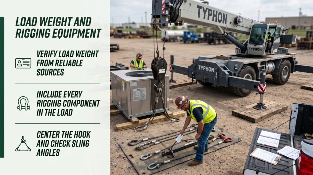
The weight that matters for a crane lift isn’t just the weight of the item being lifted. The total suspended load includes the lifted item and all applicable rigging components between the item and the crane. Depending on the crane and the load chart’s requirements, that can include the hook block or overhaul ball, slings, shackles, spreader bars, lifting beams, hooks, and any other lifting attachments.
Rigging weight adds up quickly. A heavy spreader bar, a set of wire rope slings, and several large shackles can add a significant amount to a pick, especially on a lift that’s already close to the chart limit. Weigh or confirm the rated weight of every rigging component, and add it to the load before comparing against capacity. Follow the load chart’s notes on which items must be deducted, since requirements vary between manufacturers and models.
Center of gravity matters as much as weight. A load that’s heavier on one end will tilt when lifted unless the rigging is arranged to place the hook directly above its center of gravity. A tilting load can shift in the slings, swing unexpectedly, and change the load on individual rigging components. Identify the center of gravity from the manufacturer’s information or calculations, and plan sling lengths and attachment points accordingly.
Sling angle has a major effect on rigging loads. As the angle between a sling leg and the horizontal decreases, the tension in that leg increases. A sling rated for a certain load in a vertical hitch can carry far less when used at a low angle. Use the sling manufacturer’s capacity tables for the specific hitch and angle, and select rigging rated for the actual tension, not just the load weight.
Only qualified riggers should select, inspect, and attach rigging. Use rigging with legible capacity tags, attach it only to the load’s designated lifting points, and use tag lines to control load rotation. Never allow anyone to stand under a suspended load or ride on the load or hook.
Key takeaway: The total suspended load includes the lifted item and all applicable rigging, so verify load weight from reliable sources, account for center of gravity and sling angles, and include every rigging component before comparing the lift against rated capacity.
Working Radius and Boom Configuration
Working radius is the horizontal distance from the crane’s center of rotation to the load’s lifting line, which is usually the center of the hook directly above the load. It’s one of the most important factors in mobile crane capacity. As radius increases, permitted capacity typically decreases, often sharply. A load that a crane handles easily near its base may exceed its limits only a short distance farther out.
The reason is leverage. The farther a load sits from the crane’s center of rotation, the greater the tipping force it creates. Doubling the radius of the same load roughly doubles its overturning effect. That’s why the crane in the school scenario could handle all three units at the planned radius, but the heaviest unit came too close to the limit once the setup point moved.
Radius must be measured, not estimated. Measure the actual distance from the crane’s center of rotation to the point where the load will be picked and to the point where it will be set. Both positions matter, since a load picked close to the crane may need to be set at a much longer radius. Check the radius at every point along the swing path, too. If the load passes over a position farther from the crane during the move, that position governs capacity.
Radius can also change during the lift. When a boom takes on load, it deflects slightly, which can increase radius. Swinging a suspended load can cause it to drift outward. On hydraulic telescopic cranes, extending the boom while holding the boom angle increases radius. Plan with a margin that accounts for these changes rather than planning to the exact chart limit.
Boom configuration ties directly to radius. For a given boom length, a lower boom angle produces a longer radius and lower capacity. A longer boom extension reaches farther but typically reduces capacity at a given radius compared with a shorter boom. Jibs and extensions add reach and height but have their own load charts and deductions. Telescopic booms may also have extension modes or sequences that affect capacity, so follow the manufacturer’s procedure for the extension mode in use.
Using the correct load chart entry requires matching every element of the setup. Identify the actual boom length, boom angle, radius, counterweight, outrigger position, and working area. When the exact radius or boom length falls between two chart values, follow the manufacturer’s instructions for interpolation. Many charts require using the next longer radius or longer boom length, which gives the lower capacity.
Key takeaway: Lifting capacity generally decreases as working radius increases, so measure the radius at the pick point, the set point, and along the swing path, and use the load chart entry that matches the crane’s actual boom length, angle, and configuration.
Ground Conditions and Outrigger Support
A mobile crane transfers its weight and lifting forces to the ground through its tires or outriggers. Weak soil, buried structures, or poor outrigger setup can cause settlement and increase the risk of tipping.
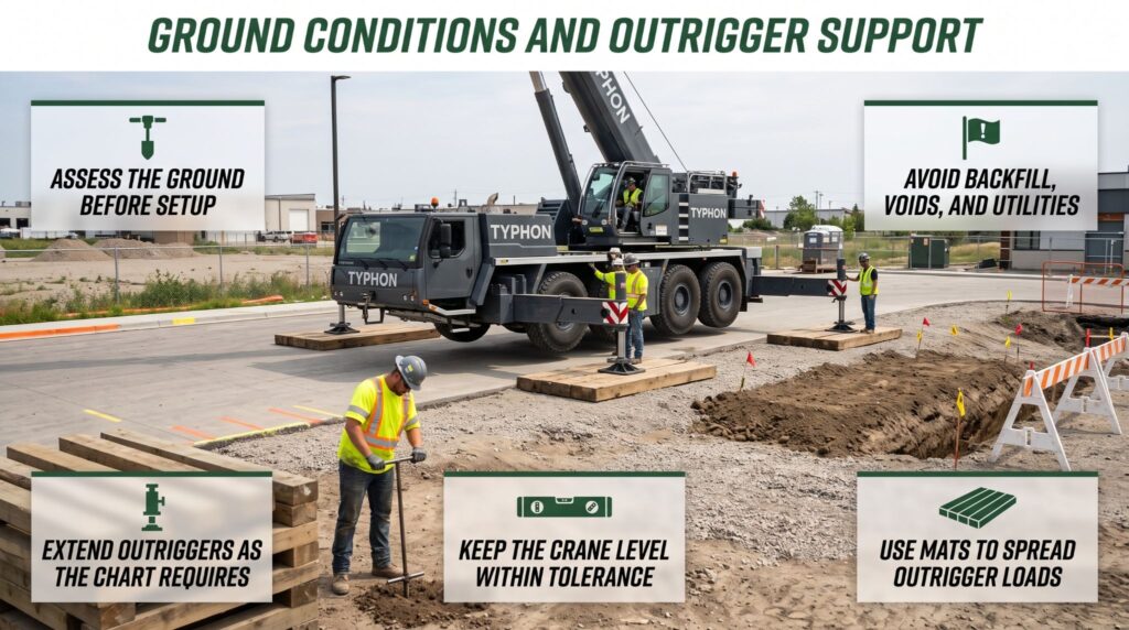
- Ground Assessment: Inspect the setup area for soft soil, slopes, excavation edges, buried utilities, and underground structures before positioning the crane.
- Outrigger Extension: Deploy outriggers according to the manufacturer’s requirements and use the load chart that matches the actual outrigger configuration.
- Support Mats and Pads: Use suitable crane mats or engineered pads to distribute outrigger loads across a larger area and reduce ground pressure.
- Crane Leveling: Level the crane within the manufacturer’s specified tolerance and confirm the setup using the level indicators.
- Settlement Monitoring: Recheck ground conditions and crane level during operation, especially after rain or ground movement. If an outrigger settles, stop the lift and correct the setup before continuing.
Key takeaway: Weak or uneven ground can compromise crane stability even when the load is within the chart limit, so assess the setup area, deploy outriggers exactly as the load chart requires, use suitable mats, and keep the crane level throughout the lift.
Wind and Environmental Conditions
Wind is one of the most underestimated forces in crane operations. It pushes against the boom and the suspended load, adds side loading the crane wasn’t designed to carry, and can cause the load to swing or rotate. A load that’s well within the chart limit in calm air can become difficult to control, or unsafe, once the wind picks up.
The load’s shape matters as much as its weight. Large, flat, or awkwardly shaped items, such as rooftop units, wall panels, roof trusses, glass panels, and formwork, have a large surface area that catches the wind like a sail. A relatively light panel with a large surface area can be harder to control than a heavy, compact load. Wind can also lift and spin these loads unexpectedly as they clear surrounding structures.
Follow the manufacturer’s wind limits. Most crane manufacturers specify maximum permissible wind speeds for operation, and those limits may vary by boom length and configuration. Some charts also include reduced capacity for loads with large surface areas in wind. Keep in mind that wind speed often increases with height, so the speed at the boom tip can exceed the speed measured on the ground. Where available, use the crane’s anemometer, and monitor both sustained winds and gusts throughout the lift.
Check the forecast during lift planning. Schedule large-surface-area lifts for calmer periods, such as early morning, when practical. Establish a wind limit for each lift in advance, and make sure everyone understands that operations stop when that limit is reached. Use tag lines handled by trained workers to control load rotation, and never wrap a tag line around a hand or body.
When conditions exceed permitted limits, stop the operation. Lower the load to a safe position, secure the crane according to the manufacturer’s procedure, and wait for conditions to improve.
Key takeaway: Wind affects the stability and movement of suspended loads, especially large or awkwardly shaped items, so follow the manufacturer’s wind limits, account for power lines, visibility, and nearby structures, and stop operations whenever conditions exceed permitted limits.
Lift Planning and Equipment Inspection
Every crane lift needs a plan, and the more complex or demanding the lift, the more detailed that plan should be. A well-prepared lift plan brings together everything covered in this guide: the load, the crane configuration, the ground, the environment, and the people involved. It’s the step that turns a capable crane into a safe and productive lift.
Many organizations classify certain lifts as critical lifts, which require a more detailed written plan and additional review. Common triggers include lifts above a set percentage of the crane’s rated capacity, lifts involving multiple cranes, lifts over occupied areas or critical equipment, and lifts near power lines. Follow your company’s policy and any project requirements for critical lift planning and approval.
Assign clear roles before the lift begins. The crane operator should be qualified or certified as required for the crane type and jurisdiction. Riggers and signal persons should be qualified for their tasks. A lift director or supervisor should oversee the operation and have the authority to stop the lift. Hold a pre-lift briefing so everyone understands the plan, their role, the signals in use, and the conditions that will stop the work. Confirm that the crane’s hydraulic flow operates correctly and supports the required lifting movements. Anyone on site should be able to call a stop when they see a hazard.
Never check for hydraulic leaks by running a hand along a hose. Pressurized fluid can penetrate skin and cause serious injury, so use a piece of cardboard instead. Remove any damaged rigging from service immediately, and tag out any crane with a defect that affects safe operation until it has been repaired. In addition to daily checks, cranes require more detailed periodic and annual inspections by qualified persons. Record inspections, findings, and repairs, and keep documentation available on site.
Key takeaway: A planned lift identifies the load, crane configuration, swing path, rigging method, communication, and exclusion zone, and both the crane and every lifting accessory must be inspected according to the required procedures before operation.
Conclusion
Mobile crane lifting capacity is never a single number, and safe lifting comes from understanding how each factor shapes the limits of every individual pick: rated capacity applies only to a specific configuration and operating condition, so the correct load chart entry, every required deduction, and a properly configured rated capacity limiter form the foundation of every lift. Working radius and boom configuration change permitted capacity significantly, which makes accurate measurement at the pick point, set point, and along the swing path essential. Verifying load weight, accounting for center of gravity, and including all rigging keep the total suspended load within limits, while firm ground, correctly deployed outriggers, suitable mats, and a level setup let the crane deliver the capacity its chart promises. Wind, power lines, visibility, and nearby structures can make even a light lift unsafe, so permitted limits must be respected and operations stopped when conditions change. A thorough lift plan, clear roles, and consistent inspection of the crane and lifting accessories tie these elements together into dependable, controlled operations on every project. Before your next lift, measure the actual radius, verify the load and rigging weight, assess the ground beneath every outrigger, check the forecast against the manufacturer’s wind limits, and brief the full crew on the lift plan so every pick stays safely within established limits.
Frequently Asked Questions
What determines a mobile crane’s lifting capacity?
A mobile crane’s lifting capacity depends on its boom configuration, working radius, counterweight, outrigger setup, load characteristics, and rated load chart. The crane’s configuration must match the conditions planned for the lift, including boom length, boom angle, and any required operating restrictions. Operators should consult the correct load chart for the actual setup before lifting. Staying within the specified limits helps maintain stability and reduces the risk of overloading the crane.
Does lifting capacity remain the same at every radius?
No. A mobile crane’s permitted lifting capacity changes with the working radius and boom configuration, and it generally decreases as the radius increases. A longer horizontal reach creates greater overturning forces, which can limit the weight the crane may safely lift. The radius should be checked at the pick point, set point, and along the swing path because the load’s distance from the crane can change during movement. Always verify the planned lift against the applicable load chart.
Why is ground support important?
Ground support is essential because the crane’s weight and lifting forces transfer to the ground through its tires or outriggers. Weak soil, uneven surfaces, buried voids, or recently disturbed ground can cause settlement and compromise stability, even when the load is within the rated capacity. Before lifting, assess the ground’s ability to support the expected loads and use suitable outrigger mats or pads where required. Keep the crane level and follow the manufacturer’s setup requirements throughout the operation.
Does the rigging weight count toward the load?
Yes. The weight of applicable hooks, slings, shackles, spreader bars, and other lifting accessories must be accounted for according to the crane’s load chart and operating requirements. These components contribute to the total suspended load and can reduce the remaining capacity available for the material being lifted. Before starting the lift, confirm the weight of the load and all relevant accessories, then compare the total against the permitted capacity for the crane’s actual configuration and working radius.